Motor Used
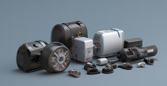
Can you provide some examples of applications where multi-motor drives are used ?
Multi-motor drives are used in various applications where multiple motors need to be controlled simultaneously, including industrial automation, CNC machines, electric vehicles, wind turbines, robotics, and aerospace.
Can a single motor drive be used for heavy-duty tasks ?
A single motor drive can indeed be used for heavy-duty tasks, but it depends on several factors such as the type of motor, its power rating, and the nature of the task. There are various types of motors available, each with its own set of advantages and disadvantages. The power rating of a motor is an important factor to consider when determining whether it can handle heavy-duty tasks. The nature of the task is another critical factor to consider. By carefully considering these factors and choosing the right motor for the job, you can ensure that your system is reliable, efficient, and effective.
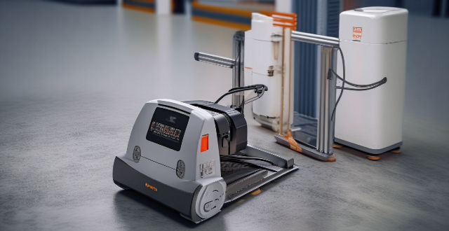
Can an AC stepping motor be used in robotics applications ?
AC stepping motors can be used in robotics applications, offering precise control and high torque. However, they have speed limitations and can overheat, requiring cooling mechanisms. Consider application requirements and compatibility with control systems before choosing an AC stepping motor for a robotic project.
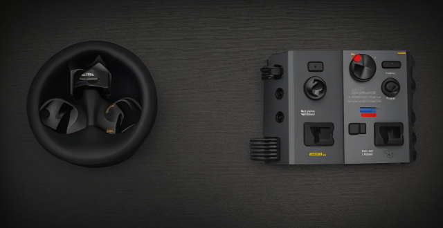
Can a speed controller be used to control the speed of an electric motor ?
A speed controller is a device that adjusts the electrical power supplied to an electric motor to change its speed. There are several types of speed controllers available for electric motors, including variable frequency drives (VFDs), DC motor controllers, and phase controllers. Using a speed controller has benefits such as energy efficiency, improved performance, extended motor lifespan, and enhanced safety.
What is the difference between single motor and multi-motor drives ?
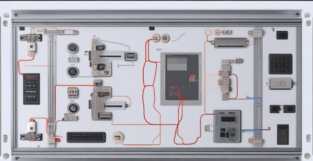
Single motor drives control only one motor and are simple, cost-effective, and easy to maintain. Multi-motor drives control multiple motors simultaneously and offer increased flexibility, improved performance, and enhanced functionality but are more complex and expensive. The choice between these two types of drives depends on the specific requirements of the application.
What is a hub motor ?
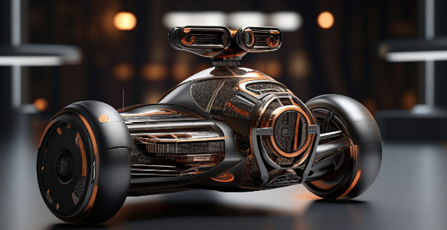
A hub motor is an electric motor integrated into a vehicle's wheel hub, offering direct drive, simplified design, quiet operation, and space efficiency. However, it has limitations such as limited power output, overheating concerns, and cost considerations. Hub motors are commonly used in electric vehicles like bicycles, scooters, motorcycles, and cars.
How does a single motor drive work ?
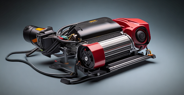
The motor drive converts incoming AC power to DC, controls the motor's speed via PWM, regulates its torque by monitoring current and adjusting voltage, and ensures proper operation through feedback control.
What is an internal rotor motor ?
The text discusses the design, advantages, disadvantages, and applications of internal rotor motors. Internal rotor motors are a type of electric motor where the moving part (rotor) is inside the stationary part (stator). They offer benefits such as high efficiency, good heat dissipation, simplicity in construction, and low inertia. However, they also have limitations like limited torque density, difficulty in cooling, and potential for magnetic saturation. These motors are commonly used in automotive, aerospace, industrial equipment, and consumer electronics applications.
Can a combination motor drive improve energy efficiency in my facility ?
Combination motor drives can improve energy efficiency in facilities by optimizing electric motor performance, reducing energy consumption, and extending equipment lifespan. They offer variable speed control, soft start/stop capabilities, and reactive power compensation features that contribute to lower energy bills, reduced maintenance costs, and environmental benefits like reduced greenhouse gas emissions.
How does the design of a permanent magnet motor differ from an induction motor ?
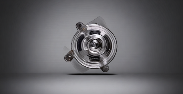
The article discusses the differences between permanent magnet motor and induction motor design, focusing on three main aspects: rotor design, stator winding design, and cooling system. The rotor of a permanent magnet motor contains high-energy rare-earth magnets that interact with the stator windings to produce torque, while the rotor of an induction motor has aluminum or copper bars that induce currents when exposed to a rotating magnetic field produced by the stator windings. The stator winding design also varies between the two types of motors, with permanent magnet motors typically having a three-phase distributed winding and induction motors having either a distributed or concentrated winding. Finally, the cooling system design differs as well, with permanent magnet motors often relying on natural convection or forced air cooling, while induction motors may use external fans or blowers for more effective heat removal. Understanding these differences is crucial for engineers to choose the appropriate motor type for their needs and optimize its performance accordingly.
What are the different types of combination motor drives available in the market ?
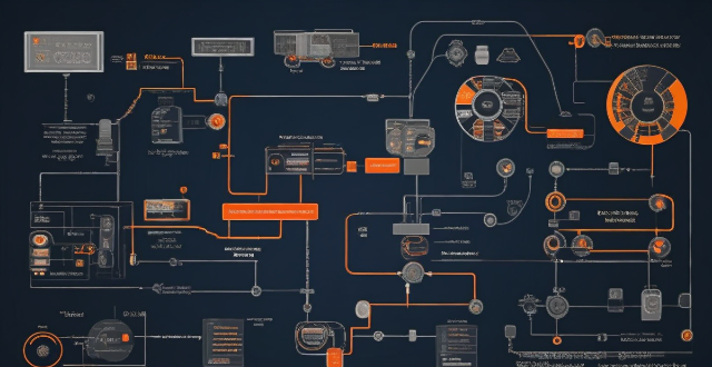
The article discusses different types of combination motor drives, including AC, DC, servo, and stepper motor drives. It highlights their unique features such as precise speed control, high torque output, regenerative braking, position control, feedback systems, and microstepping capabilities. The article emphasizes the importance of selecting the appropriate type of motor drive based on the specific needs and requirements of the application.

How does a combination motor drive work ?
Combination motor drives integrate VFD and servo controller functionalities to achieve precise speed and torque control for AC induction and permanent magnet synchronous motors. They enhance performance, reduce energy consumption, and extend motor lifespan by offering smooth speed control and reducing wear and tear. Key components include a VFD, servo controller, electric motor, encoder, and user interface. The system uses feedback from an encoder to adjust the motor's input signals, ensuring accurate motion profiles.
How does a multi-motor drive system work ?
The text explains how a multi-motor drive system works, its components, and benefits. It describes the process of power conversion, control signals, motor operation, mechanical transmission, and feedback adjustment in such systems. The advantages include improved efficiency, increased redundancy, and enhanced control.
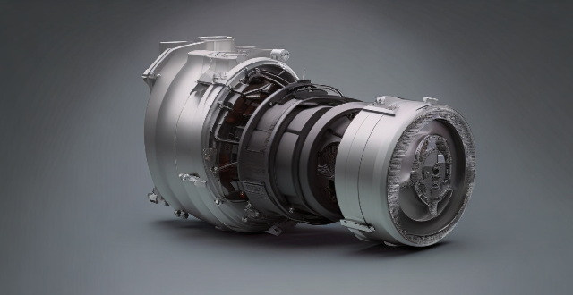
What is a brushless motor ?
Brushless motors, also known as BLDC (Brushless Direct Current) motors, are electric motors that use an electronic controller to switch the current in their stator windings. They have higher efficiency, longer lifespan, higher power density, lower maintenance requirements, and quieter operation compared to brushed motors. The working principle of a brushless motor involves three main components: the rotor, stator, and electronic controller. Brushless motors are used in various applications, including aircraft, automotive, appliances, and industrial equipment.
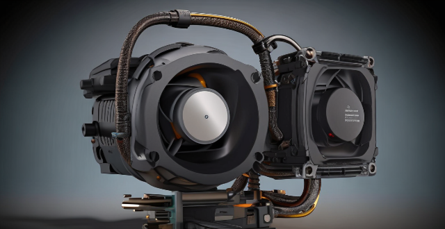
How does a single motor drive compare to a dual motor drive ?
This article compares single motor drives and dual motor drives based on their performance, efficiency, cost, and applications. Single motor drives can only control one motor at a time, while dual motor drives can control two motors simultaneously. Dual motor drives offer higher overall torque and better synchronization between multiple motors, but they also consume more power and require more maintenance. Single motor drives are typically less expensive and well-suited for low power applications with simple movement profiles, while dual motor drives are appropriate for high power applications with complex movement profiles requiring precise synchronization. The choice between a single motor drive and a dual motor drive depends on the specific requirements of the application.

What are the benefits of using a combination motor drive system ?
Combination motor drive systems offer benefits such as improved efficiency, increased reliability, flexibility, and enhanced control. These systems combine the advantages of different types of motors to create a more efficient and reliable drive system. They are ideal for a wide range of applications and can help businesses save money on energy costs while reducing downtime and maintenance requirements.
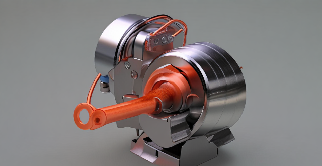
What is the typical cost difference between a permanent magnet motor and an equivalent size induction motor ?
Permanent magnet motors (PMMs) and induction motors (IMs) are two common types of electric motors used in various applications. The cost difference between them is often a significant factor in deciding which one to use. PMMs are known for their high efficiency, compact size, and low noise levels, while IMs are simpler and more robust. The cost difference depends on factors such as size, power rating, materials used, and manufacturing processes. Generally, PMMs are more expensive than IMs of equivalent size due to material costs, manufacturing processes, efficiency and performance requirements, and market demand and availability. When choosing between these two types of motors, it is essential to consider both the technical requirements and budget constraints of your specific application.
Can an electronic speed controller be used in a car engine ?
The question of whether an electronic speed controller (ESC) can be used in a car engine depends on the type of engine. In traditional internal combustion engines (ICE), which use gasoline or diesel as fuel, an ESC cannot be used because these engines rely on mechanical systems for speed control. However, in electric cars, which use electric motors as their primary source of propulsion, an ESC is essential for controlling the speed of the motor and protecting it from damage. Therefore, while an ESC cannot be used in ICE vehicles, it plays a crucial role in electric vehicles.

How much power can a hub motor generate ?
Hub motors are electric motors built into the wheel's hub and are commonly found in electric vehicles, wheelchairs, and other space-limited applications. The power generation of a hub motor is influenced by its design, size, and the type of battery it uses. Larger motors generally produce more power but require more energy to operate. The control system managing the motor's power output can also affect performance. Examples of hub motor power generation include small electric bikes (250-500 watts), medium electric bikes (500-1000 watts), large electric bikes (over 1000 watts), electric wheelchairs (250-1000 watts), and other applications like golf carts and electric cars with varying power ratings.
How do you choose the right AC stepping motor for your project ?
Choosing the right AC stepping motor requires understanding project needs, selecting the appropriate motor type, ensuring compatibility with control systems, considering physical constraints, evaluating performance characteristics, accounting for environmental factors, managing budgetary considerations, relying on supplier support and reputation, and conducting thorough testing.

Can an electromagnetic motor be used for renewable energy production ?
This article explores the potential of electromagnetic motors for renewable energy production, highlighting their efficiency, reliability, scalability, and low maintenance costs. It also discusses their applications in wind turbines, hydroelectric power plants, solar power plants, and geothermal power plants. However, it acknowledges some potential disadvantages such as high initial cost, complex control systems, and compatibility issues that should be considered when evaluating their suitability for a particular project.
Can hub motors be used in bicycles ?
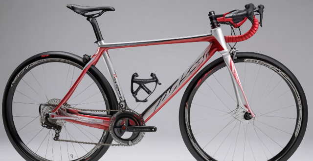
Hub motors, built into the wheel's hub, are compact and lightweight, making them suitable for bicycles. They offer easy installation, quiet operation, and low maintenance but may have limited power output and reduced range. Hub motors are designed for specific wheel sizes and can be more expensive than other electric motors. Despite some disadvantages, they are a popular choice for DIY e-bike projects and those seeking electric power assistance without sacrificing performance or handling characteristics.
In what applications is a single motor drive commonly used ?
Single motor drives are used in various applications for precise control of speed, torque, and position. These applications include industrial automation (robotics, conveyor systems, packaging machines), transportation (EVs, hybrid vehicles, drones), home appliances (washing machines, dishwashers, refrigerators), HVAC systems (air conditioners, heat pumps, ventilation systems), and agriculture (irrigation systems, farm equipment, greenhouses).
Can you explain the concept of vector control in multi-motor drives ?
Vector control is a method for controlling the speed and torque of electric motors, especially AC motors, in multi-motor drives. It works by decoupling the flux-producing and torque-producing components of the stator current, allowing for independent control of both. This results in improved dynamic response, precise speed regulation, energy efficiency, reduced mechanical stress, and adaptability to different motor types.
Are permanent magnet motors more susceptible to damage from high temperatures compared to other motor types ?
Permanent magnet motors are more susceptible to high temperatures due to demagnetization and thermal expansion issues, compared to induction motors and switched reluctance motors which primarily face insulation degradation and material fatigue respectively.
Are there any safety concerns associated with using a combination motor drive ?
The text discusses the safety concerns associated with using combination motor drives, which combine the functions of an electric motor and a gearbox. Safety issues include electrical hazards such as overheating and electrical shock, mechanical hazards like gearbox failure and injuries from rotating parts, and chemical hazards from lubricants and fluids. To ensure safe operation, it is important to follow proper safety procedures, regularly maintain the equipment, and use appropriate personal protective equipment.
What is the efficiency rate of an internal rotor motor compared to other types of motors ?
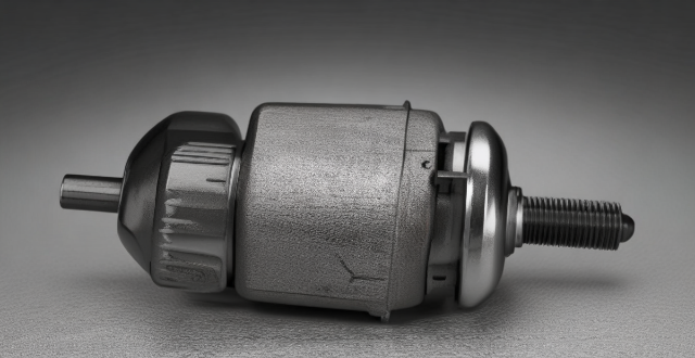
The efficiency rate of an internal rotor motor compared to other types of motors depends on various factors such as design, size, application, materials, and control system. Internal rotor motors typically have higher efficiency rates than external rotor motors due to their compact design and reduced air gap between the rotor and stator. However, it is essential to consider the specific requirements of the application when choosing a motor type, as other factors such as brushless DC (BLDC) motors and permanent magnet synchronous motors (PMSM) are also known for their high efficiency rates.
Can you explain the differences between an internal and external rotor motor ?
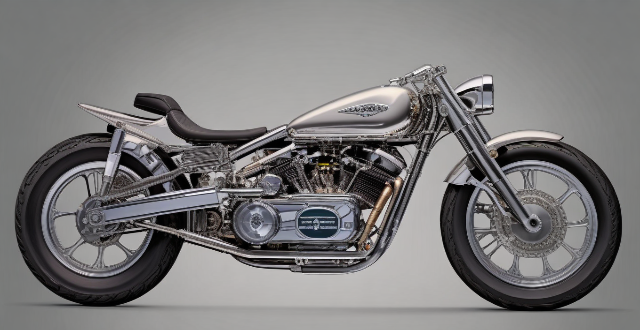
Motors are crucial components of various mechanical systems, and understanding their types is essential for selecting the appropriate one for a specific application. Two common types of motors are internal rotor motors and external rotor motors. An internal rotor motor has its rotor located inside the stator, while an external rotor motor has its rotor located outside the stator. The main differences between these two types of motors include rotor location, torque output, cooling efficiency, maintenance accessibility, and application suitability. Understanding these differences can help in selecting the appropriate motor type for a given task.

What is an AC stepping motor and how does it work ?
An AC stepping motor is a type of electric motor that operates on alternating current and moves in discrete steps. It is commonly used in applications requiring precise control, such as robotics, CNC machines, 3D printers, and automation systems. The motor's movement is achieved by energizing its coils in a specific sequence, causing the rotor to turn a fixed angle for each step. The components of an AC stepping motor include the stator, rotor, and drive system. The stator is the stationary part of the motor containing coils or windings. The rotor is the rotating part of the motor, which has magnetic teeth. The drive system controls the sequence and timing of electrical pulses sent to the stator coils. The operational principle of an AC stepping motor involves winding energization, rotor alignment, stepping action, and repeating sequence. When an electrical current is applied to the stator windings, it creates a magnetic field. The magnetic field interacts with the rotor's magnetic teeth, causing them to align with the stator's field. By changing the sequence of the energized coils, the rotor is forced to rotate to a new position where the teeth again align with the stator's magnetic field. Continuously changing the energized coils causes the rotor to move in a series of small steps. There are two phases of operation for an AC stepping motor: single phase and multi-phase. Single phase operates using only one phase of AC power, typically for simpler applications. Multi-phase uses multiple phases of AC power for more complex movements and higher torque requirements. Control and drive systems for an AC stepping motor include microstepping, drivers, and controllers. Microstepping allows the motor to move in even smaller steps than its inherent step angle by controlling the current through the windings. The driver translates digital commands into the appropriate current levels and patterns required by the motor. The controller sends commands to the driver based on input from sensors or user interfaces. Advantages of an AC stepping motor include precision, simple control, and high reliability. Disadvantages include low top speed, resonance issues, and torque drop-off. In summary, an AC stepping motor converts electrical pulses into discrete mechanical movements through the interaction of its stator and rotor components. Its operational simplicity and precision make it ideal for various control applications despite some limitations in speed and resonance concerns.
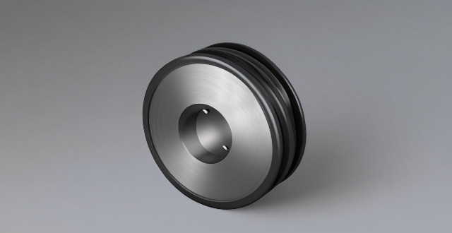
How does the design of a DC brushed motor impact its performance and efficiency ?
The performance and efficiency of a DC brushed motor are significantly influenced by its design. Key factors include the materials used, winding configuration, magnet strength, bearing type, and cooling system. Materials such as silicon steel for stator cores and carbon steel or aluminum alloys for rotor cores affect magnetic properties and mechanical strength. Winding configuration, including the number of poles and winding type (lap or wave), determines speed and torque characteristics. Magnet strength, shape, and placement impact torque production and power density. Bearing type (ball or roller) affects precision, friction, and load capacity. Finally, proper cooling through active or passive methods is essential for preventing overheating during operation. Overall, careful consideration of these design elements is crucial for achieving desired motor performance and efficiency goals.